

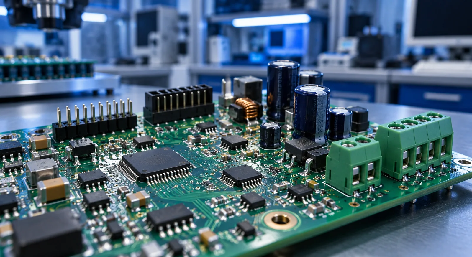
1. Distinguish SMD, SMT and THT
SMD describes a surface-mount device, while SMT describes surface-mount technology. THT is through-hole technology, where component leads pass through holes in the PCB. The distinction concerns the connection to the board, rather than simply whether the component is large or small. A large power device may be surface mounted, while a small connector may use through-hole leads.
Do not plan production from appearance alone. Review the complete ordering code, manufacturer drawing and board footprint together. Changing a package calls for more than editing pad dimensions: assembly access, mechanical placement and the relationship with nearby parts should also be reviewed before the layout is released.
2. Compare approaches against the board requirements
SMT is widely used for dense layouts and automated placement. Through-hole options often appear among connectors, relays and larger mechanical items. However, broad claims such as “THT is always stronger” or “SMD is always cheaper” are poor design rules. The outcome depends on component geometry, board support, production volume and the validated manufacturing process.
Instead of naming an unconditional winner, decide how each relevant requirement will be verified in your product.
| Decision | SMD / SMT considerations | THT considerations |
|---|---|---|
| Board area | Supports dense placement | Holes and lead access occupy space |
| Mechanical load | Review body and pad support | Review hole connection and body support |
| Process flow | Plan paste, placement and reflow | Plan insertion and suitable soldering |
| Service | Package may need dedicated rework tools | Preserve holes and maintain lead access |
| Inspection | Distinguish visible and hidden joints | Assess access around holes and joints |
3. Discuss the process sequence for mixed assembly
A typical SMT sequence applies solder paste, places components and uses reflow soldering. Through-hole joints may use wave, selective or manual soldering according to the product and process requirements. A mixed board commonly passes through SMT processing before through-hole assembly, but the actual sequence depends on the parts fitted to both sides and the selected methods.
Do not assume every component tolerates every thermal process. Manufacturer assembly documents contain package-specific limits and recommendations. The Texas Instruments mounting guide illustrates why package and process conditions need to be considered together. Identify heat-sensitive connectors, tall components and mechanical items fitted later in the build.
4. Provide a deliberate path for mechanical loads
A cable that is connected and removed repeatedly applies force to its connector and solder joints. The choice is broader than SMD versus THT: retention features, mechanical anchors, enclosure spacing and the direction of cable pull also matter. If the board bends substantially during connection, changing the mounting technology alone may leave the underlying problem unresolved.
For example, a control board with field-wiring terminals may need mounting holes and enclosure support positioned with screwdriver forces in mind. A lightweight internal communications module presents a different load case, so surface-mount connections may be suitable when validated for that use. Include the mechanical designer in the review alongside the electronics engineer.
5. Plan inspection, testing and service access together
A tidy assembled board is not proof of correct function. Visual review, appropriate inspection methods and functional testing answer different questions. Build a test plan around the product: supply rails, programming, communications and response under meaningful loads may all matter. Access to test points is an early layout decision regardless of the mounting technologies chosen.
Connections hidden under a package cannot be assessed in the same way as visible leads. Select inspection methods according to package features and the risks being checked. If service is expected, also consider whether tall through-hole parts obstruct rework of neighbouring SMD devices. A small component placed immediately beside a large connector may be easy to fit during initial assembly yet difficult to reach during repair.
6. Apply the decision to a control-board example
Consider a small industrial controller with a surface-mount microcontroller, transceiver and passive components, plus through-hole field terminals and some mechanical connections. This is a plausible starting arrangement, not an automatically optimal design. The team first checks enclosure fit and cable access, then discusses process sequence and component suitability with the assembler.
Compare quotations against the same scope. In addition to the number of placements, identify SMT and THT items, populated sides, testing requirements and responsibility for supplying material. This makes it easier to understand whether a price difference comes from component purchasing, setup or an additional assembly operation.
- Confirm complete part codes and mounting styles in the BOM.
- Review connector loads, board support and enclosure fit.
- Agree the sequence for both board sides and mixed soldering.
- Check thermal limits in manufacturer documentation.
- Review programming, test and service access before release.
Frequently asked questions
Can SMD and THT components be used on one PCB?
Yes. Mixed assembly uses both approaches. Process order, component suitability, populated board sides and soldering access need to be planned together.
Is SMD assembly always less expensive?
No. Volume, setup, component variety, double-sided processing, testing and additional operations affect the total. Compare quotations using the same files and scope.
Should prototypes use THT and production boards use SMD?
There is no mandatory split. Using production packages can help a prototype represent the final product. The choice depends on the learning goal, available components and validation plan.
Conclusion and next step
The SMD versus THT decision connects electrical function with manufacturing and mechanical requirements. Reviewing individual parts, documenting assembly needs and planning test access make a mixed board easier to prepare for production.
Share your PCB assembly requirements
For a PCB assembly enquiry, share your BOM, Gerbers, available placement file and testing expectations with RoseVia so the mounting and assembly scope can be reviewed.
Technical references
The following manufacturer and technical organization documents provide further detail. Use the selected component’s current data sheet for product-specific limits.