

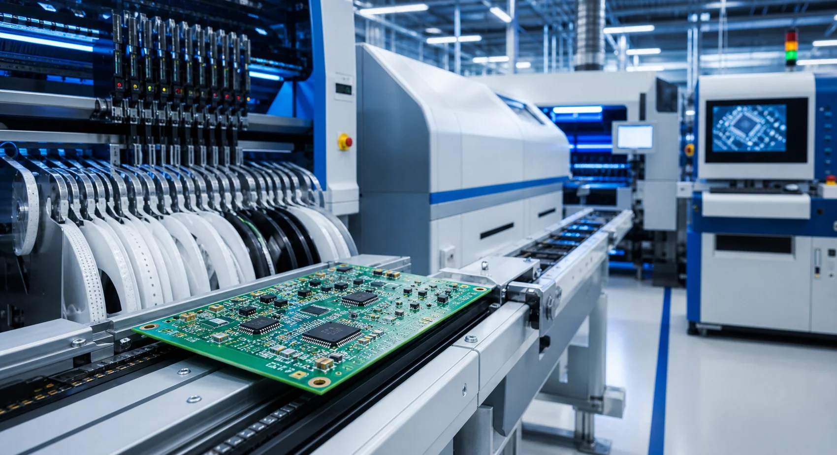
Electronic board manufacturing is not a single handoff from design to factory. File integrity, sourcing, bare-board fabrication, assembly, soldering, inspection, and functional verification form one connected process. Managing eight essential stages with explicit acceptance criteria makes both quality and delivery planning more predictable as a project moves from prototype to volume.
How should the process be evaluated?
A dependable technical process does more than arrange tasks in sequence. It defines the input, output, owner, and evidence for each stage. When a requirement changes, the team should be able to identify the affected design files, tests, and sourcing decisions. This reduces repeated work and communication loss in both small prototypes and production programs.
The sections below are not a universal recipe. Voltage, environment, volume, safety impact, and certification needs change the appropriate depth of control. A practical method makes risk visible early, turns verification into measurable evidence, and keeps technical files synchronized with every approved change.
Stages 1–2: Validate the production inputs
Project-file review
Schematics, layout, mechanics, firmware, and test expectations must reference the same revision. Missing notes, ambiguous polarity, or enclosure conflicts are resolved before a purchase order creates avoidable rework.
A sound decision about project-file review considers tolerances, operating limits, and credible fault conditions—not only nominal values. Recording the input, evidence, and engineering decision in a short note prevents the same uncertainty from returning in later revisions. It also gives manufacturing, test, and service teams a shared technical reference.
A review of project-file review can be concise, but the evidence behind the decision should remain visible. A checklist, measurement record, approved sample, or captured result makes the verification repeatable. When a deviation appears, the team traces the requirement, design, and process chain instead of repairing only the visible symptom, reducing the chance of moving risk elsewhere.
Gerber and BOM preparation
Copper, drill, outline, mask, and legend data are reviewed in a CAM viewer. BOM entries include manufacturer part numbers, packages, quantities, tolerances, and any alternatives that engineering has actually approved.
The depth of control for gerber and bom preparation should match project risk and production volume. A manual prototype check may need a fixture, automated measurement, or explicit work instruction at scale. The purpose is not to add ceremony; it is to catch meaningful defects in a repeatable way before they reach the customer.
Risks associated with gerber and bom preparation may not appear on the first sample. They often emerge when temperature, load, vibration, or component tolerance changes. Verification should therefore include realistic operating scenarios, credible worst cases, and diagnostic information that a maintenance team can access rather than relying only on ideal laboratory conditions.
Stages 3–4: Source parts and fabricate PCBs
Component sourcing
Availability, lead time, traceability, storage requirements, and lifecycle risk are considered together. Long-lead or critical parts are secured early, and substitutions are never introduced without design approval.
Component sourcing should not be treated as an isolated discipline. Electrical performance, mechanics, firmware behavior, sourcing, and maintenance may all influence the same decision. An early cross-functional review exposes uncertainty while changes are still inexpensive and keeps the delivery plan grounded in real constraints.
After component sourcing is completed, the team checks consistency between files and the physical product. The approved revision, fitted components, programmed firmware, and test result are linked through traceability records. This simple discipline makes it easier to identify an affected batch during field analysis and avoids unnecessarily broad corrective action.
PCB fabrication
Material, stack-up, copper weight, finish, geometry limits, and controlled-impedance requirements are confirmed with the fabricator. Electrical test and panelization requirements are matched to the intended build volume.
When acceptance criteria for pcb fabrication are defined in advance, the result is more useful than a simple pass or fail. The test condition, expected range, equipment, and response to a deviation are documented. Prototype and production results can then be compared consistently, creating better evidence for root-cause analysis.
The cost discussion around pcb fabrication should include more than initial engineering time. Detection during production, field downtime, rework, logistics, and support load may dominate the real cost of a defect. Early control can appear to add effort, yet it closes high-impact uncertainty while change is still relatively inexpensive.
Stages 5–6: Assemble and solder
SMD and THT assembly
Stencil data, paste print, placement programs, and component orientation are verified through first-article inspection. THT parts need a defined sequence, mechanical support, and an appropriate wave, selective, or manual process.
A sound decision about smd and tht assembly considers tolerances, operating limits, and credible fault conditions—not only nominal values. Recording the input, evidence, and engineering decision in a short note prevents the same uncertainty from returning in later revisions. It also gives manufacturing, test, and service teams a shared technical reference.
A review of smd and tht assembly can be concise, but the evidence behind the decision should remain visible. A checklist, measurement record, approved sample, or captured result makes the verification repeatable. When a deviation appears, the team traces the requirement, design, and process chain instead of repairing only the visible symptom, reducing the chance of moving risk elsewhere.
Soldering processes
The reflow profile must suit the paste, board thermal mass, and component limits. Heat-sensitive devices, large copper areas, and mixed-technology assemblies often need additional process controls.
The depth of control for soldering processes should match project risk and production volume. A manual prototype check may need a fixture, automated measurement, or explicit work instruction at scale. The purpose is not to add ceremony; it is to catch meaningful defects in a repeatable way before they reach the customer.
Risks associated with soldering processes may not appear on the first sample. They often emerge when temperature, load, vibration, or component tolerance changes. Verification should therefore include realistic operating scenarios, credible worst cases, and diagnostic information that a maintenance team can access rather than relying only on ideal laboratory conditions.
Stage 7: Inspect the assembly
Visual inspection
Polarity, missing or incorrect parts, bridges, insufficient solder, mechanical damage, and cleanliness are checked under controlled conditions. Documented criteria prevent acceptance from changing with the individual inspector.
Visual inspection should not be treated as an isolated discipline. Electrical performance, mechanics, firmware behavior, sourcing, and maintenance may all influence the same decision. An early cross-functional review exposes uncertainty while changes are still inexpensive and keeps the delivery plan grounded in real constraints.
After visual inspection is completed, the team checks consistency between files and the physical product. The approved revision, fitted components, programmed firmware, and test result are linked through traceability records. This simple discipline makes it easier to identify an affected batch during field analysis and avoids unnecessarily broad corrective action.
Automated and measurement-based checks
AOI, X-ray, electrical measurement, or ICT may be used when the risk and volume justify them. No single method detects every defect; effective coverage comes from choosing complementary checks.
When acceptance criteria for automated and measurement-based checks are defined in advance, the result is more useful than a simple pass or fail. The test condition, expected range, equipment, and response to a deviation are documented. Prototype and production results can then be compared consistently, creating better evidence for root-cause analysis.
The cost discussion around automated and measurement-based checks should include more than initial engineering time. Detection during production, field downtime, rework, logistics, and support load may dominate the real cost of a defect. Early control can appear to add effort, yet it closes high-impact uncertainty while change is still relatively inexpensive.
Stage 8: Verify function and scale
Prototype validation and functional test
A board is tested against its operating range, not merely for power-up. Programming, communication, I/O, load, thermal behavior, and protection scenarios are verified with recorded results.
A sound decision about prototype validation and functional test considers tolerances, operating limits, and credible fault conditions—not only nominal values. Recording the input, evidence, and engineering decision in a short note prevents the same uncertainty from returning in later revisions. It also gives manufacturing, test, and service teams a shared technical reference.
A review of prototype validation and functional test can be concise, but the evidence behind the decision should remain visible. A checklist, measurement record, approved sample, or captured result makes the verification repeatable. When a deviation appears, the team traces the requirement, design, and process chain instead of repairing only the visible symptom, reducing the chance of moving risk elsewhere.
Transition to mass production
Pilot-build yield, defect patterns, cycle time, and test capacity are reviewed before scale-up. An approved golden sample, revision lock, traceability, and formal change control become the production references.
The depth of control for transition to mass production should match project risk and production volume. A manual prototype check may need a fixture, automated measurement, or explicit work instruction at scale. The purpose is not to add ceremony; it is to catch meaningful defects in a repeatable way before they reach the customer.
Risks associated with transition to mass production may not appear on the first sample. They often emerge when temperature, load, vibration, or component tolerance changes. Verification should therefore include realistic operating scenarios, credible worst cases, and diagnostic information that a maintenance team can access rather than relying only on ideal laboratory conditions.
Conclusion and next step
Controlled manufacturing links all eight stages instead of treating them as separate suppliers or tasks. RoseVia can support file review, sourcing, prototype and production coordination, and test preparation within the agreed project scope.
Reviewing the technical scope, production objective, and available project files together is the most reliable way to choose the next step.