

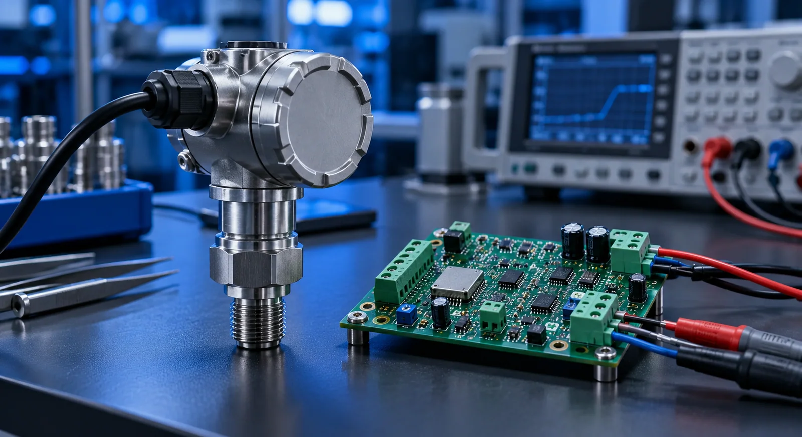
Identify what powers and controls the loop
A two-wire loop-powered transmitter and a separately powered current output may need different wiring. In a loop-powered installation, supply, sensor and receiver share a series current path. Identify active or passive outputs, the loop supply and reference terminal from the manufacturer drawing.
Before selecting components, record the engineering range, normal output range, fault-current behavior and minimum operating voltage. One pressure sensor may represent zero pressure with 4 mA while another is configured for an entirely different lower limit. The words “4–20 mA” do not define the physical unit or measurement span. Put both the electrical interface and the engineering configuration into the product requirements.
Choose the shunt for the ADC and available headroom
For a simple receiver, V = I × R. A worked example using 150 Ω produces 0.6 V at 4 mA and 3.0 V at 20 mA. This is an example value, not a universal recommendation. Check the ADC input limits, reference tolerance and any sensor current beyond the normal range before committing to a resistance. Leave deliberate headroom where the system requires abnormal-current measurement.
At 20 mA the example resistor dissipates P = I²R = 0.06 W. Consider this power together with temperature rise and resistance tolerance. A higher resistance uses more ADC span but consumes more loop voltage. For comparison, 250 Ω produces 1–5 V, which is not directly suitable for a 3.3 V ADC input. Protection components cannot compensate for a normal signal range that already exceeds the input rating.
| Current | Voltage across 150 Ω | Example 0–10 bar value |
|---|---|---|
| 4 mA | 0.6 V | 0 bar |
| 12 mA | 1.8 V | 5 bar |
| 20 mA | 3.0 V | 10 bar |
Check the loop voltage budget at the worst condition
The receiver, cable, protection and other series devices consume part of the supply voltage. Suppose the minimum supply is 21.6 V, the sensor requires 12 V, the receiver drops 3 V and other losses total 2 V. Margin is 4.6 V. Use actual specifications rather than these example assumptions.
Do not check only nominal 24 V with a short cable. Cable resistance, supply tolerance and the highest supported current can change the result. A receiver that cannot reach full scale in the installation may have insufficient voltage margin. Include a full-scale test at minimum supply with the intended cable.
Distinguish ADC resolution from measurement accuracy
For an ideal 12-bit ADC with a 3.3 V range, one count is approximately 0.806 mV. With the example 150 Ω resistor, this represents about 5.37 µA, or approximately 0.00336 bar over a 0–10 bar span. This is a quantization calculation. It is not a claim about the finished board accuracy, the sensor accuracy or the smallest reliable process change.
Build a separate error budget for shunt tolerance, temperature coefficient, ADC offset and gain, reference drift, leakage and noise. Check the ADC sampling input requirements as well. A slowly changing signal does not mean that any large resistor and capacitor can drive the sample-and-hold input correctly. Evaluate settling time, source impedance and, where required, a buffer amplifier with a suitable layout.
Keep scaling, calibration and status separate
For the 0–10 bar example, pressure = (I_mA − 4) × 10 / 16. A traceable conversion sequence first turns the ADC code into calibrated voltage, then calculates current from the actual shunt value, and finally applies the engineering range. Store lower and upper engineering limits as configuration rather than embedding one pressure formula into every sensor channel.
Two known current points can establish offset and gain calibration; verify intermediate points too. Preserve raw samples, filtered values and validity status separately. Clamping low currents to zero can disguise a broken cable. Set fault thresholds from transmitter documentation and application requirements, and expose invalid data to operators and control logic.
Verify protection, filtering and the complete signal chain
Transient protection, an analog input filter and a digital average perform different jobs. A software filter cannot protect hardware against an overvoltage or wiring fault. Excessive averaging can also hide a real pressure change for too long. Define an acceptable settling time from the process requirements, apply a current step and measure how long the displayed value takes to reach the required tolerance.
Use a suitable current source or loop calibrator to test the first board independently of the sensor. Record raw codes and calculated units at lower, middle and upper points. Then repeat with the real transmitter, installed cable and operating cabinet. This sequence separates transmitter configuration, receiver gain and site interference. Keep the calibration constants with the board revision so a later component change does not silently reuse an unsuitable conversion.
- Confirm polarity and the active or passive loop arrangement.
- Verify the normal measurement range and documented fault currents.
- Test cable disconnection, power restoration and filter settling time.
Frequently asked questions
Can a 4–20 mA sensor connect directly to an ADC pin?
Usually an input stage is needed to convert current into a suitable voltage. Design the shunt, protection, loop wiring and ADC limits together.
Is 250 Ω always the correct receiver resistor?
No. It produces 5 V at 20 mA. If the ADC range or loop voltage budget cannot accommodate that result, use a different resistance or input architecture.
Should a broken cable be displayed as zero?
Invalid data should have a separate status. Use documented fault behavior and appropriate thresholds to distinguish disconnection from a valid zero process measurement.
Conclusion and next step
A useful 4–20 mA input defines the whole chain, from loop voltage through ADC conversion to sensor status. Combine the calculations with calibration and installation tests to make the resulting measurement understandable and traceable.
Discuss Your Analog Sensor Input Design
Technical references
The following manufacturer and technical organization documents provide further detail. Use the selected component’s current data sheet for product-specific limits.