

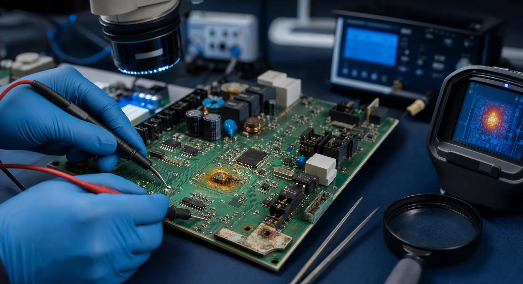
Circuit board failures rarely have a one-to-one relationship between symptom and cause. A dead output may originate in a short, unstable supply, damaged driver, broken trace, firmware state, or mechanical connector. Safe diagnosis starts with an unpowered inspection, controlled measurement, and a systematic understanding of how the circuit is expected to operate.
How should the process be evaluated?
A dependable technical process does more than arrange tasks in sequence. It defines the input, output, owner, and evidence for each stage. When a requirement changes, the team should be able to identify the affected design files, tests, and sourcing decisions. This reduces repeated work and communication loss in both small prototypes and production programs.
The sections below are not a universal recipe. Voltage, environment, volume, safety impact, and certification needs change the appropriate depth of control. A practical method makes risk visible early, turns verification into measurable evidence, and keeps technical files synchronized with every approved change.
Electrical damage and failed components
1. Short circuits
Solder bridges, damaged devices, incorrect assembly, or conductive contamination can produce a short. Unpowered resistance checks and current-limited bench testing help localize the fault without escalating damage.
A sound decision about 1. short circuits considers tolerances, operating limits, and credible fault conditions—not only nominal values. Recording the input, evidence, and engineering decision in a short note prevents the same uncertainty from returning in later revisions. It also gives manufacturing, test, and service teams a shared technical reference.
A review of 1. short circuits can be concise, but the evidence behind the decision should remain visible. A checklist, measurement record, approved sample, or captured result makes the verification repeatable. When a deviation appears, the team traces the requirement, design, and process chain instead of repairing only the visible symptom, reducing the chance of moving risk elsewhere.
2. Burned components
Discoloration or cracking may be visible, but the root cause is often overvoltage, reverse polarity, excessive current, or inadequate cooling. Replacing only the visibly damaged part may lead to an immediate repeat failure.
The depth of control for 2. burned components should match project risk and production volume. A manual prototype check may need a fixture, automated measurement, or explicit work instruction at scale. The purpose is not to add ceremony; it is to catch meaningful defects in a repeatable way before they reach the customer.
Risks associated with 2. burned components may not appear on the first sample. They often emerge when temperature, load, vibration, or component tolerance changes. Verification should therefore include realistic operating scenarios, credible worst cases, and diagnostic information that a maintenance team can access rather than relying only on ideal laboratory conditions.
Interconnect and solder defects
3. Cold solder joints
Dull, cracked, or ring-shaped joints can become intermittent under vibration and thermal cycling. Magnified inspection and continuity checks are especially useful around connectors and mechanically heavy parts.
3. Cold solder joints should not be treated as an isolated discipline. Electrical performance, mechanics, firmware behavior, sourcing, and maintenance may all influence the same decision. An early cross-functional review exposes uncertainty while changes are still inexpensive and keeps the delivery plan grounded in real constraints.
After 3. cold solder joints is completed, the team checks consistency between files and the physical product. The approved revision, fitted components, programmed firmware, and test result are linked through traceability records. This simple discipline makes it easier to identify an affected batch during field analysis and avoids unnecessarily broad corrective action.
4. Broken PCB traces
Impact, overcurrent, poor rework, or corrosion can interrupt copper. Before repair, the trace current, layer transitions, clearances, and any safety function must be understood.
When acceptance criteria for 4. broken pcb traces are defined in advance, the result is more useful than a simple pass or fail. The test condition, expected range, equipment, and response to a deviation are documented. Prototype and production results can then be compared consistently, creating better evidence for root-cause analysis.
The cost discussion around 4. broken pcb traces should include more than initial engineering time. Detection during production, field downtime, rework, logistics, and support load may dominate the real cost of a defect. Early control can appear to add effort, yet it closes high-impact uncertainty while change is still relatively inexpensive.
Environmental and power-supply faults
5. Oxidation and moisture
Moisture combined with ionic residue creates leakage and corrosion. Inspection should include connector pins, via fields, and areas beneath components rather than only the visible stain.
A sound decision about 5. oxidation and moisture considers tolerances, operating limits, and credible fault conditions—not only nominal values. Recording the input, evidence, and engineering decision in a short note prevents the same uncertainty from returning in later revisions. It also gives manufacturing, test, and service teams a shared technical reference.
A review of 5. oxidation and moisture can be concise, but the evidence behind the decision should remain visible. A checklist, measurement record, approved sample, or captured result makes the verification repeatable. When a deviation appears, the team traces the requirement, design, and process chain instead of repairing only the visible symptom, reducing the chance of moving risk elsewhere.
6. Power-supply failures
Fuses, rectifiers, regulators, capacitors, and feedback elements form one chain. Ripple, undervoltage, or unstable startup may require controlled load testing in addition to static voltage checks.
The depth of control for 6. power-supply failures should match project risk and production volume. A manual prototype check may need a fixture, automated measurement, or explicit work instruction at scale. The purpose is not to add ceremony; it is to catch meaningful defects in a repeatable way before they reach the customer.
Risks associated with 6. power-supply failures may not appear on the first sample. They often emerge when temperature, load, vibration, or component tolerance changes. Verification should therefore include realistic operating scenarios, credible worst cases, and diagnostic information that a maintenance team can access rather than relying only on ideal laboratory conditions.
Drivers, communication, and heat
7. Relay and MOSFET problems
Contact wear, coil-drive faults, gate resistance, protection diodes, or switching loss can cause failure. Diagnosis must consider the actual load and transient conditions seen by the device.
7. Relay and MOSFET problems should not be treated as an isolated discipline. Electrical performance, mechanics, firmware behavior, sourcing, and maintenance may all influence the same decision. An early cross-functional review exposes uncertainty while changes are still inexpensive and keeps the delivery plan grounded in real constraints.
After 7. relay and mosfet problems is completed, the team checks consistency between files and the physical product. The approved revision, fitted components, programmed firmware, and test result are linked through traceability records. This simple discipline makes it easier to identify an affected batch during field analysis and avoids unnecessarily broad corrective action.
8. Communication problems
Logic levels, termination, grounding, cabling, connectors, addressing, and firmware settings can all create similar symptoms. The physical layer and protocol behavior should be verified separately.
When acceptance criteria for 8. communication problems are defined in advance, the result is more useful than a simple pass or fail. The test condition, expected range, equipment, and response to a deviation are documented. Prototype and production results can then be compared consistently, creating better evidence for root-cause analysis.
The cost discussion around 8. communication problems should include more than initial engineering time. Detection during production, field downtime, rework, logistics, and support load may dominate the real cost of a defect. Early control can appear to add effort, yet it closes high-impact uncertainty while change is still relatively inexpensive.
Thermal, mechanical, and economic limits
9. Overheating
Excess current, poor thermal contact, insufficient copper, airflow, or control-loop faults raise temperature. Thermal imaging is useful only when measurements are performed under safe, defined load conditions.
A sound decision about 9. overheating considers tolerances, operating limits, and credible fault conditions—not only nominal values. Recording the input, evidence, and engineering decision in a short note prevents the same uncertainty from returning in later revisions. It also gives manufacturing, test, and service teams a shared technical reference.
A review of 9. overheating can be concise, but the evidence behind the decision should remain visible. A checklist, measurement record, approved sample, or captured result makes the verification repeatable. When a deviation appears, the team traces the requirement, design, and process chain instead of repairing only the visible symptom, reducing the chance of moving risk elsewhere.
10. Mechanical damage and repair economics
Broken connectors, cracked boards, or lifted pads may be repairable, but internal multilayer damage, safety-critical use, or widespread corrosion can make repair unreliable or uneconomic.
The depth of control for 10. mechanical damage and repair economics should match project risk and production volume. A manual prototype check may need a fixture, automated measurement, or explicit work instruction at scale. The purpose is not to add ceremony; it is to catch meaningful defects in a repeatable way before they reach the customer.
Risks associated with 10. mechanical damage and repair economics may not appear on the first sample. They often emerge when temperature, load, vibration, or component tolerance changes. Verification should therefore include realistic operating scenarios, credible worst cases, and diagnostic information that a maintenance team can access rather than relying only on ideal laboratory conditions.
Conclusion and next step
Effective fault finding gathers evidence before replacing parts. Where the project information and physical condition allow, RoseVia can support board inspection, measurement, root-cause assessment, and a practical repair-versus-replacement decision.
Reviewing the technical scope, production objective, and available project files together is the most reliable way to choose the next step.